Hemispherical Infrared - Hardware
This page describes the hardware for the camera, from the overall geometry to the electronics and the holders
What is this about ?
This camera is a system containing: servos mounted in a pan tilt configuration; imaging infrared sensor; potentially lidar sensor; onboard computation and power. This page describes the various aspects and choices that were made. The goal here was to arrive as a good working prototype relatively quickly so obviously pretty much everything can be optimized or improved, I will be glad to hear your thoughts on that !
This page contains a few sections covering the different aspects, I would advise to start with the overall architecture section and dig further in the topic that are of interest for you.
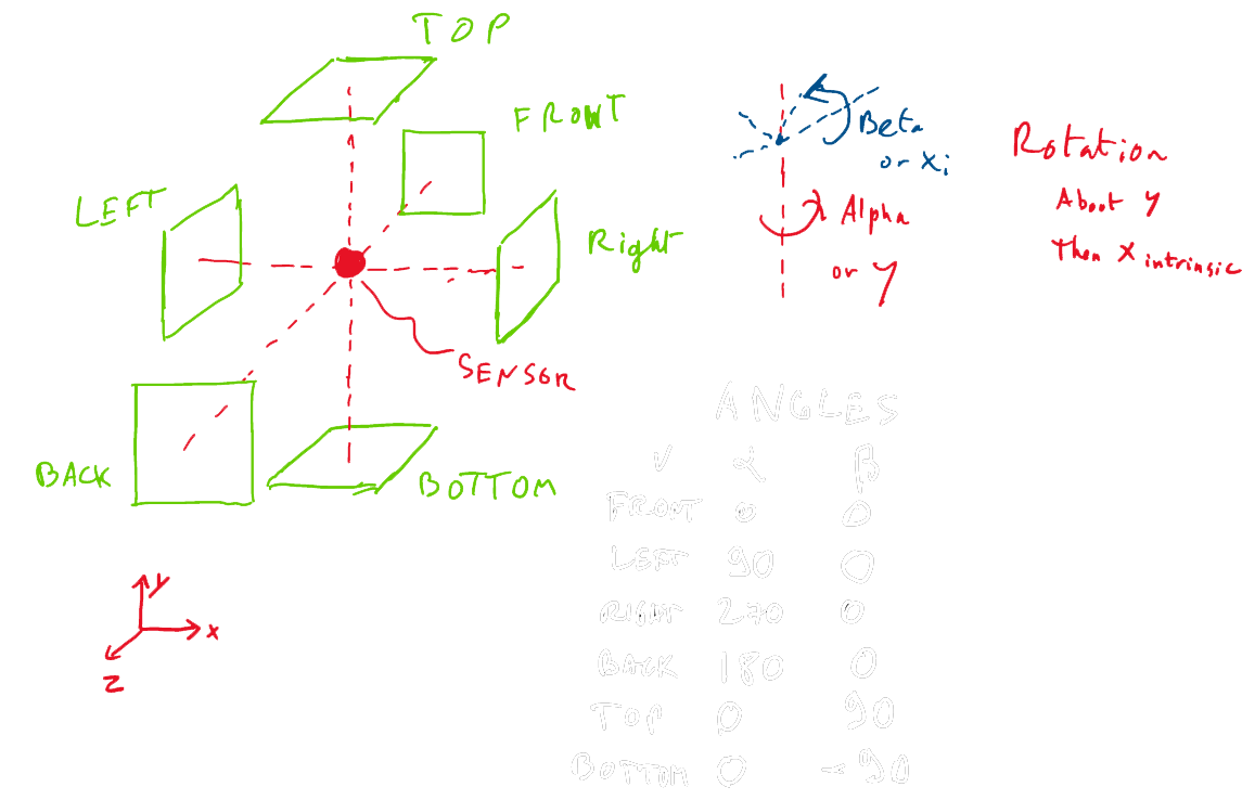
If any angular notation is confusing, please refer to the Angles convention section
Current hardware and rationale
This is the overall hardware view architecture.

The current choice for the component is the following
- Compute: Raspberry pi 0/3
- Time: qwiic sparkfun RTC
- Power: Dual voltage rechargeable battery. 12V/5V (TalentCell 12V 3000mAh)
- Power/data merge: Hand soldered/screw plug or interbotics power hub or robotis SMPS2Dynamixel
- Infrared sensor: Melexis MLX90640 on a sparkfun board
- Potential lidar: TfMini serial version (the i2c version was burning the Melexis on the i2c bus) Sparkfun link
- Servos: Robotis Dynamixel MX-12W
- Communication for servo: Robotis U2D2
This is a pan tilt system with communication, i2c, serial and logging. The rationale on the different components is quickly explained below.
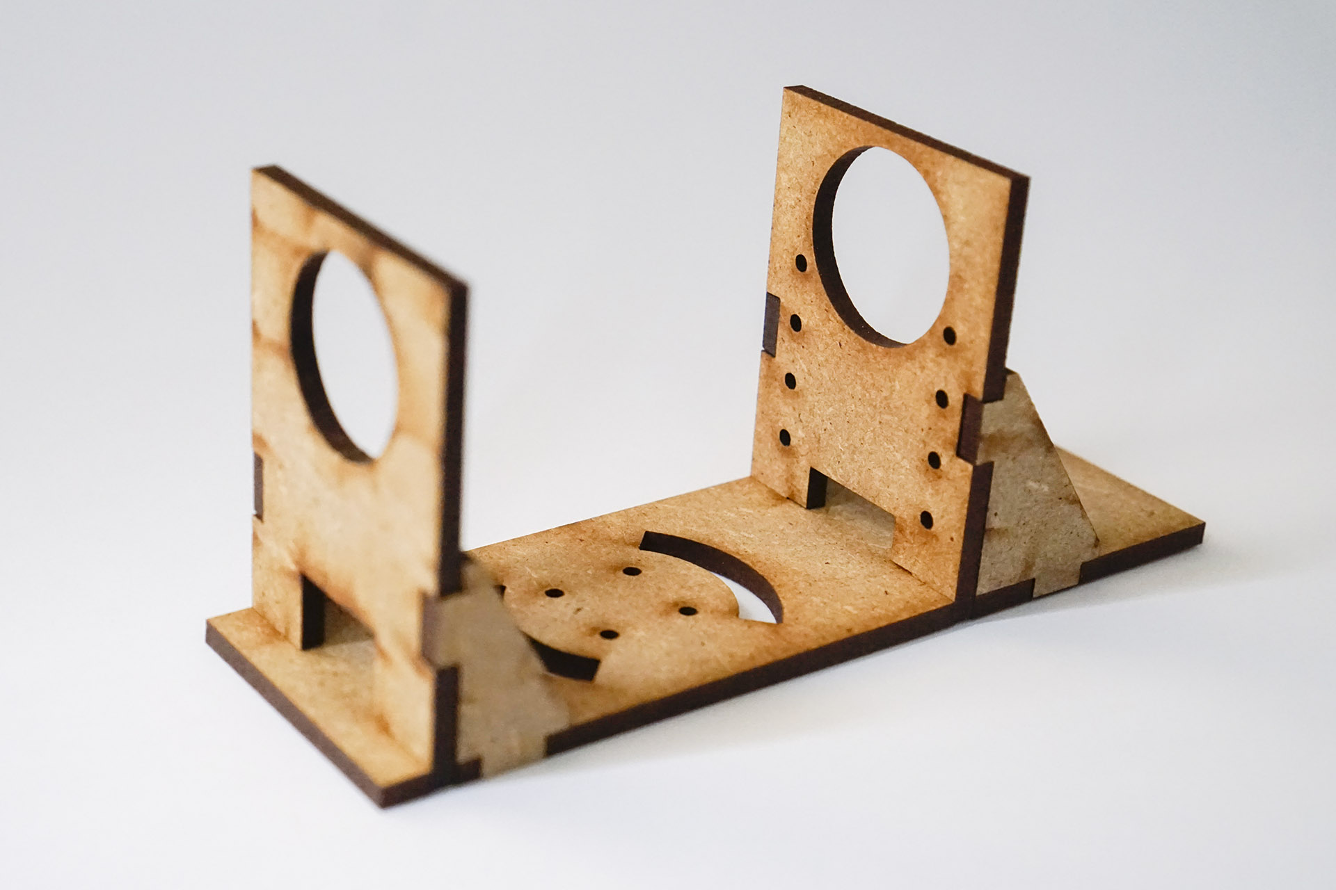
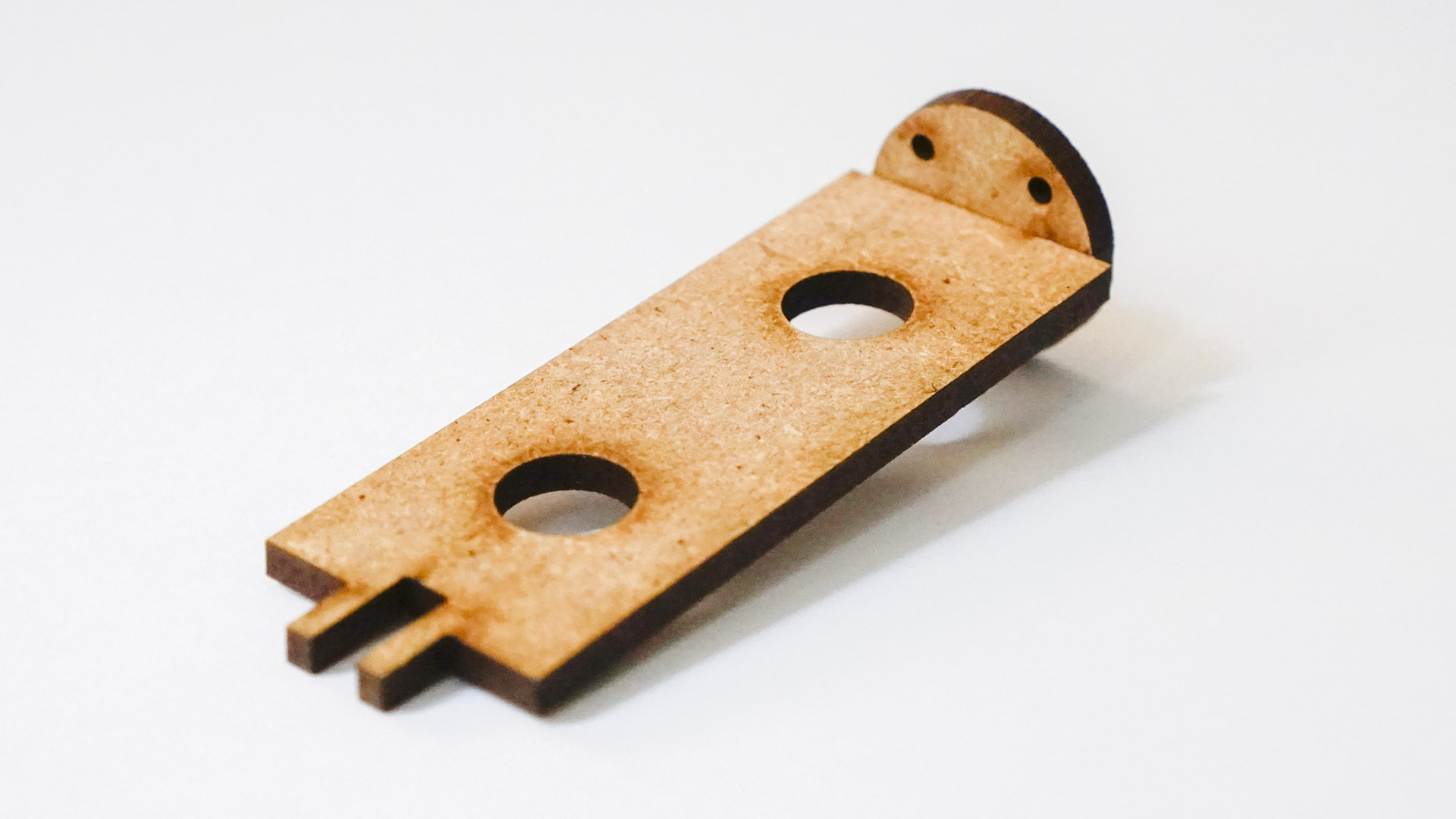
Hold it together
PICTURE
You can download the dxf for laser cutting (3mm medium, 200um trace) here
This is what the box without sensor look like (more images in the Photos section)
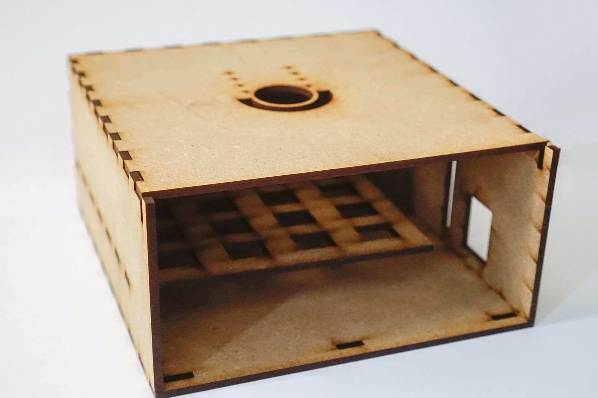
The bottom box is pretty large to be flexible and with a middle shelves with holes for cable routing. The design of the front door can be improved as sliding it can proove difficult at times.
Servos
Which one, why ?
The Melexis sensor is 32 pixels for a 55 degrees FOV, which is a 1.5 Degree wide pixel. If one want to upgrade to the FLIR Lepton 2.5 modules we have 80 pixels for 50 degree FOV so about 0.75 degree wide pixels. FLIR lepton 3.5 is 120px for 57 degrees, so 0.5 degrees pixels.
If we want to take full advantage of the sensor resolution we need to have a sub pixel angular positioning. If we want to do super resolution even better as image resolution is quite low to realign the images with standard RANSAC techniques.
To obtain an hemispherical image we need ideally 360 degree rotation. (We can do with less in some cases, see the Software page for angle optimization)
I found relatively inexpensive closed loop digital PID servos with tunable parameters and 4096points per rotation from Robotis. The “limitation” of these servos is that they need an extra 12V power supply and have a half duplex TTL bus that need a special adapter to interface with the computing part. For the sake of simplicity I use the Robotis U2D2 but there are plenty others on the market. The bus is a three wire bus: GND, DATA, PWR. So a very small board or hand soldering allow for GND,PWR + GND, DATA --> GND,DATA,PWR
PID parameters
These are the parameters for getting the MX-12W moving and with good accuracy, not too fast. Please refer to the dynamixel documentation for further information on the meaning of those values.
| Field Name | Value |
|---|---|
| TORQUE_LIM | 250 |
| D_GAIN | 5 |
| I_GAIN | 12 |
| P_GAIN | 12 |
| MOVING_SPEED | 80 |
| CW_LIM | 0 |
| CCW_LIM | 4095 |
| ACCELERATION | 10 |
| PUNCH | 10 |
The other values are left to the factory defaults.
Angle conversion
The following figure displays the Dynamixel MX-12W angles to servo instruction.
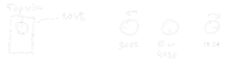
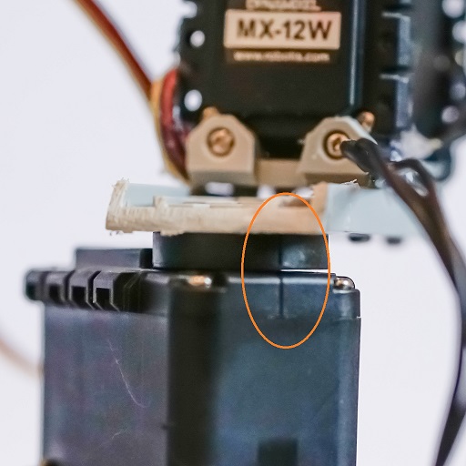
The software converts this and an angle of 0 correspond to the notches aligned. These are a few pictures of the prototype at different angles. Versus the overall convention of the cubemap (see Angles convention) for mounting considerations, it’s easier to mount with a 45 degree offset on the Y/vertical axis. If you want to redo the camera, feel free to drill a few holes in a mount so the 0 will be aligned the way you want !
Another important parameter to have in mind, if there is no divider set (aka multiturn mode), when going the servo crosses 0 (ie from 0 to 4095 or 4095 to 0) at the angle goal, it will do a full turn through all the values.
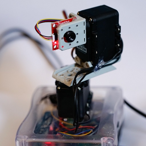
Vertical rotation (Y) 0, Horizontal rotation (Xi) 0
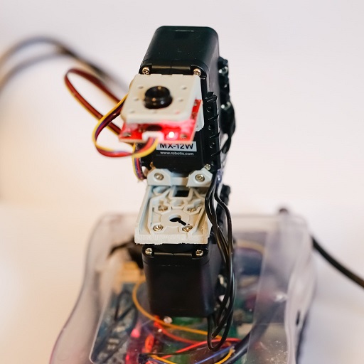
Vertical rotation (Y) 45, Horizontal rotation (Xi) 90
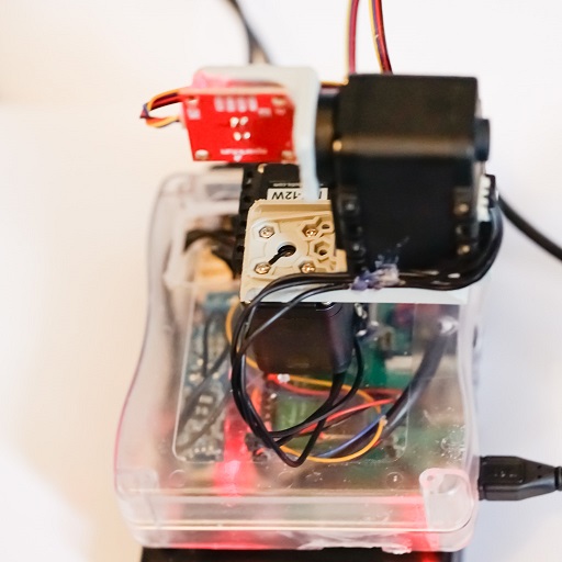
Vertical rotation (Y) -45, Horizontal rotation (Xi) 180
Power
As stated in the servos section, the servos need a 12V power supply. The raspberry pi and most uC runs on 5V (some on 3.3V) so we need those two voltages. For the sake of simplicity I have picked a dual 12V/5V rechargeable battery pack (from TalentCell). This is a good prototype solution but I would prefer a USB rechargeable solution and a more integrated battery solution.
Computation
In terms of computation, there is very little processing necessary to be done on the system itself. The code is written in C++ thus portable to a lot of embedded systems once the communication drivers are adapted. A raspeberry pi is honestly overkill for the task but is pretty practical for development and already contains logging and communication (but no RTC :-( )
Sensors
The goal for this project is to see what can be done in the infrared area with low cost sensors, wide angle, time resolve capture and data processing. The cheapest sensor that still produce an image in 2020 is the Melexis MLX90640. It has a limitted resolution (32x24 pixels) but is very simple to operate via i2c. The drawback is the communication speed which is a significant fraction of the acquisition time (estimated ~25%). An upgrade can be a FLIR Lepton.
It can be interesting to merge infrared data with depth/geometry data. I am currently experimenting with a TfMini “Lidar” sensor. The L in this lidar stands for LED which decrease significantly the cost, but give a bigger measurement spot.
What I think could be improved
A lot can be improved here, pretty much everything but this is a functional base.
The power system is not great. I think it will be simpler to use a standard rechargeable 5V battery as the market is full of inexpensive ones and design a small power board that can do the voltage conversion, includes the chip for the TTL bus and the connections to the uC, sensors and servo. The way these batteries on/off switch works is also weird. If it’s on OFF BUT charging, everything is powered.
Other servo options can be explored, just to name a few:
- There is a miniature version, with less angular resolution (1024 points), angular limitation (300 degree range), different voltage (7.4V): DYNAMIXEL XL-320
- There is another robotis, roughly equivalent but other mounting XL430-W250T
- Same as above but two servos combined, will make mounting easier but no control of paralax: 2XL430-W250-T. Could still be an interesting option
Angles convention
Here are the conventions used for the angles in this project
Project maintained by Brice Dubost-Vedrenne Theme jekyll-theme-midnight by mattgraham modified by Brice Dubost-Vedrenne

This work is licensed under a Creative Commons Attribution-NonCommercial-ShareAlike 4.0 International License.